
PTFE-coated absorbers instead of fragile dome


Overview
The NR-LITE2 is a rugged net radiometer that measures the energy balance between incoming short-wave and long-wave infrared radiation relative to surface-reflected short-wave and outgoing long-wave infrared radiation. It is directly connected to a Campbell Scientific datalogger and is widely used in agriculture and hydrology applications.
Read MoreBenefits and Features
- Compatible with most Campbell Scientific data loggers
- Integrated bubble level ensures proper installation
- Includes rod that deters birds from roosting on the radiometer
- PTFE-coated absorbers are weather resistant without using a fragile plastic dome
Technical Description
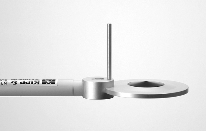
The NR-LITE2 includes two black conical absorbers—one facing upward and the other facing downward. The absorbers are coated in PTFE, making them resistant to weather without using a fragile plastic dome. Both absorbers are calibrated to an identical sensitivity coefficient.
The NR-LITE2 has a bubble level to ensure proper installation and a rod that deters birds from roosting on the sensor. It produces a millivolt signal that is measured directly by a Campbell Scientific datalogger.
Images

Related Products
Compatibility
Please note: The following shows notable compatibility information. It is not a comprehensive list of all compatible products.
Dataloggers
| Product | Compatible | Note |
|---|---|---|
| CR1000 (retired) | ||
| CR1000X (retired) | ||
| CR300 (retired) | ||
| CR3000 | ||
| CR310 | ||
| CR350 | ||
| CR6 | ||
| CR800 (retired) | ||
| CR850 (retired) |
Additional Compatibility Information
Mounting
To avoid shading/reflections and to promote spatial averaging, the NR-LITE2 should be mounted at least 1.5 m above the ground or crop canopy and away from all obstructions or reflective surfaces that might adversely affect the measurement. Campbell Scientific recommends mounting the NR-LITE2 to a separate vertical pipe at least 25 ft away from other mounting structures. The 26120 Net Radiation Sensor Mounting Kit is used to mount the NR-LITE2 to a vertical pole or a horizontal crossarm, such as the CM202, CM203, CM204, or CM206.
Specifications
| Sensor | Two black conical absorbers—one facing upward and the other facing downward |
| Measurement Description | Measures incoming and outgoing short-wave and long-wave radiation |
| Spectral Range | 0.2 to 100 µm |
| Response Time | < 20 s (nominal) |
| Sensitivity | 10 µV W-1 m2 (nominal) |
| Output Range | ±25 mV |
| Measurement Range | ±2000 W m-2 |
| Operating Temperature Range | -40° to +80°C |
| Sensor Diameter | 8.0 cm (3.1 in.) |
| Support Arm Diameter | 1.6 cm (0.6 in.) |
| Support Arm Length | 80 cm (31.5 in.) |
| Sensor Weight | 200 g (7.0 oz) |
| Support Arm Weight | 635 g (23 oz) |
Resources and Links
Product Brochures
Manuals
FAQs for
Number of FAQs related to NR-LITE2-L: 9
Expand AllCollapse All
-
As a general guide, go at least 1.5 m above the tallest plant (tree) in an ecosystem.
-
Yes, as long as the correct AWG for the cable is used. In addition, the extension point should be water tight. The total cable length should not exceed 100 ft because signal dissipation can become too great along the cable.
-
The net radiation measurement must be scaled to give total megajoules per square meter (MJ/m2) received during the period between calling the output table with the ETsz() instruction in it. (This is normally the scan interval.) If the sensor is scaled to output flux, the value needs to be converted to megajoules. For example, if the output flux unit is W/m2, multiply the flux value by the scan interval (in seconds) and by 10-6 to convert the value to megajoules (that is, MJ = W x scan x 10-6).
-
The calibration of the NR-LITE2-L is carried out at zero wind speed. At any other wind speed, the sensitivity will decrease. It has been shown that this decrease in sensitivity is less than 1% of reading per m/s wind speed, and the effect is essentially independent of the radiation level. More information about this can be found in the "Sensitivity to Wind Speed" subsection in the "Overview" section of the instruction manual.
-
Albedo is the fraction of solar energy (short-wave radiation) reflected from the Earth back into space. It is a measure of the reflectivity of the surface of the earth. Because this sensor does not produce separate components of the long-wave and short-wave radiation, it is impossible to properly calculate the albedo.
-
As of June 2013, all of our current and retired net radiation sensors can be mounted using this kit. These include:
- Current sensors: CNR4-L, NR-LITE2-L, and NR01-L
- Retired sensors: CNR1, CNR1-L, CNR2-L, NR-LITE-L, and Q7.1-L
-
Mount the net radiometer so that no shadow will be cast on it at any time of day from obstructions such as trees, buildings, the mast, or the structure on which it is mounted.
Campbell Scientific recommends installing a net radiometer in an open area, away from the main weather station structure on a separate vertical mast. If it is necessary to install this sensor on the main tall tower (30 ft or taller), the sensor should be installed at the top of the tower. In the northern hemisphere, the sensor should be facing south. In the southern hemisphere, the sensor should be facing north. If the tower uses a solar power system (that is, solar panels), ensure that the solar panels are installed away from the main tower.
-
Because of the loss of IR radiation, nearly all thermopile instruments typically have a negative offset. This offset is most easily visible at night-time, when a small negative value is read instead of zero. This same offset is present during the daytime, but it is not as visible because of the large solar signal.
Another common issue involves leveling an instrument. Leveling a thermopile instrument can cause errors in the direct beam component because the cosine response is not correct. These errors are more notable when the sun is close to the horizon because the angle is so shallow.
-
The information included on a calibration sheet differs with each sensor. For some sensors, the sheet contains coefficients necessary to program a data logger. For other sensors, the calibration sheet is a pass/fail report.
Privacy Policy Update
We've updated our privacy policy. Learn More
Cookie Consent
Update your cookie preferences. Update Cookie Preferences