Product Line
| ISO Classification | Spectral Range | Sensitivity | Operating Temperature Range | |
|---|---|---|---|---|
SunVue 30
|
Spectrally flat Class A (ISO 9060:2018) | 285 to 2800 nm | — | -40° to +80°C |
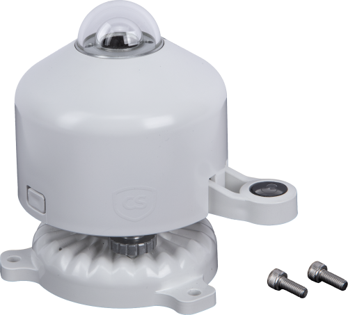
CS320
|
Class C (second class) | 385 to 2105 nm (50% points) | 0.057 mV/W/m2 | -50° to +60°C |
CS310
|
— | 389 to 692 nm ±5 nm (wavelengths where response is greater than 50% of maximum) | 0.01 mV per µmol m-2 s-1 | -40° to +70°C |
SR30-L
|
Hemispherical Solar Radiation: Spectrally flat Class A (secondary standard) ISO 9060:2018 | Hemispherical Solar Radiation: 285 to 3000 x 10-9 m | Hemispherical Solar Radiation: Digital output | Hemispherical Solar Radiation: -40 to +80°C (rated) |
CMP3-L
|
Class C (second class) | 300 to 2800 nm | 5 to 20 µV/W/m2 | -40° to +80°C |
CMP10-L
|
Class A (secondary standard) | 285 to 2800 nm | 7 to 14 µV/W/m2 | -40° to +80°C |
CMP11
|
Class A (secondary standard) | 285 to 2800 nm | 7 to 14 µV/W/m2 | -40° to +80°C |
SMP10-L
|
Class A (secondary standard) | 285 to 2800 nm (50% points) | 2-wire RS-485 Modbus | -40° to +80°C |
CMP21
|
Class A (secondary standard) | 285 to 2800 nm | 7 to 14 µV/W/m2 | -40° to +80°C |
NR-LITE2-L
|
— | 0.2 to 100 µm | 10 µV W-1 m2 (nominal) | -40° to +80°C |
NR01
|
— |
|
10 to 40 μV W-1 m2 | -40° to +80°C |
CNR4
|
— |
|
5 to 20 μV W-1 m2 | -40° to +80°C |
Other Considerations
| ISO Classification | Spectral Range | Sensitivity | Operating Temperature Range | |
|---|---|---|---|---|
SR05-L
|
Spectrally flat Class C (second class) ISO 9060:2018 | 285 to 3000 x 10-9 m | — | -40° to +80°C |
MS-80SH-L
|
|
285 to 3000 nm | ~10 µV/W/m2 | -40° to +80°C |
MS-80-L
|
|
285 to 3000 nm | ~10 µV/W/m2 | -40° to +80°C |
CS301
|
Class C (second class) | 360 to 1120 nm | 0.2 mV/W/m2 | -40° to +70°C |
SP230SS
|
Class C (second class) | 360 to 1120 nm (wavelengths where response is 10% of maximum) | 0.2 mV/W/m2 | -40° to +70°C |
CS325DM-L
|
— | — | — | -35° to +80°C |
SN500SS
|
— |
|
|
-50° to +80°C and 0 to 100% humidity |
LI200R
|
— | 400 to 1100 nm | 0.13 kW m-2 mV-1 (typically) | -40° to +65°C |


Resources and Links
Product Brochures
FAQs for
Number of FAQs related to Solar Radiation Sensors: 5
Expand AllCollapse All
-
For thermopile pyranometers, a thermopile is used within the instrument as the sensor, and the thermal gradients are measured across hot and cold areas (black and white). The radiation intensity is proportional to the temperature differences between the two sensing areas. Accuracy depends upon the sensitivity of the material used in the sensors, the response time, and the distortion characteristics of the material constituting the dome (if present) covering the sensors.
For silicon photocell pyranometers, electric current is generated by a photo-sensitive diode in proportion to solar intensity. Ordinarily, silicon photocell pyranometers are not fully sensitive to the full spectrum of visible light, and they cannot “see” a certain portion of the electromagnetic spectrum such as under cloudy conditions or vegetative canopies. Silicon photocell pyranometers will introduce errors under these conditions. In full sunlight conditions, however, they are calibrated to properly output solar radiation measurements.
-
Sometimes, an old cable can be replaced with a new, shorter cable.
Sometimes, an existing cable can be shortened by cutting the ends off. However, there are a few issues that could be encountered when doing this:
- Some sensors have bridge completion resistors at the pigtail end.
- Some sensors are calibrated to length.
- Sometimes the color in the insulation may not be the same as that visible at the pigtail end.
Because of the potential issues, do not cut the ends off any sensor cable without first contacting Campbell Scientific to discuss the sensor in detail.
-
Many times, but not always, a sensor’s cable can be replaced with a new cable. This is helpful if the original cable was damaged or if its length needs to be changed.
If the cable is attached to the sensor using a connector, Campbell Scientific will sell a replacement cable. For example, a 05106CBL-L is a replacement cable for a 05106-L. Replacement cables are listed in the “Replacement Parts” section of the Ordering information area of the product page.
If the cable is attached to a sensor through a user-accessible terminal block, a raw cable can be purchased to replace it. For example, to replace the cable on a 05103-L Wind Monitor, order the desired length of pn 9721, 24 AWG 3 Twisted Pair Shielded Santoprene Cable. As another example, the raw cable for a TE525-L Rain Gage is pn 9661, 22 AWG 1 Twisted Pair Shielded Santoprene Cable.
If the cable is an integral part of the sensor, the cable cannot be user replaced, and the sensor must be returned to Campbell Scientific. Some examples of sensors that fall into this category include the 107-L, 109SS-L, 229-L, CS547A-L, and CS650-L. For the process of returning equipment to Campbell Scientific, refer to the Repair and Calibration page.
-
Whenever possible, purchase a sensor with the desired cable length. Some sensors have a user-specified cable length, whereas other sensors have a set cable length.
Sometimes, an old cable can be replaced with a new, longer cable.
Generally, additional cable cannot be spliced onto the existing cable because:
- Some sensor cables have bridge completion resistors at the pigtail end
- Some sensors are calibrated based on cable length
- Sometimes the color in the insulation is not the same as that visible at the pigtail end
- It is possible to introduce errors or malfunctions depending on the integrity of the splice
Splicing cable together increases the likelihood that water may enter the cable and cause shorting, corrosion, and some other potential issues, which in turn can cause measurement issues.
Because of the potential issues, do not splice any sensor cable without first contacting Campbell Scientific to discuss the sensor in detail.
-
Not every sensor comes with a calibration sheet. If a calibration sheet is included, it is listed in the “Ships With” section of the sensor’s product web page or it is specified when ordered.