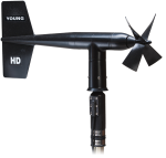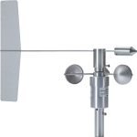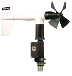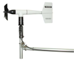
Good all purpose wind set


Overview
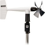
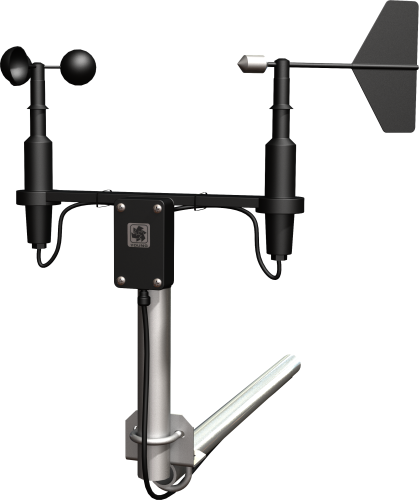
The 03002, manufactured by R. M. Young, measures wind speed and direction with a 3-cup anemometer and a wind vane mounted on a small crossarm. It interfaces directly with Campbell Scientific dataloggers; no signal conditioning is required.
Read MoreBenefits and Features
- Compatible with most Campbell Scientific data loggers
- Designed for continuous, long-term, unattended operation in adverse conditions
- Small size, simplicity, and rugged construction provide a quality instrument for a modest price
- Ideal for wind profile studies
- Compatible with the LLAC4 4-channel Low-Level AC-Conversion Module, which increases the number of anemometers one data logger can measure
- Campbell Scientific version uses shielded bearings, which lowers the anemometer's starting threshold
- Compatible with the CWS900-series interfaces, allowing it to be used in a wireless sensor network
Technical Description
The 03002 uses a cup wheel assembly to measure wind speed. Rotation of the cup wheel produces an ac sine wave that is directly proportional to wind speed. The frequency of the ac signal is measured by a datalogger pulse count channel, then converted to engineering units (mph, m/s, knots). Campbell Scientific’s version uses shielded bearings, which lowers the anemometer’s threshold.
Wind direction is sensed by a potentiometer. With the precision excitation voltage from the datalogger applied to the potentiometer element, the output signal is an analog voltage that is directly proportional to the azimuth angle of the wind direction.
Images


Compatibility
Please note: The following shows notable compatibility information. It is not a comprehensive list of all compatible products.
Dataloggers
| Product | Compatible | Note |
|---|---|---|
| CR1000 (retired) | ||
| CR1000X (retired) | ||
| CR300 (retired) | ||
| CR3000 | ||
| CR310 | ||
| CR350 | ||
| CR6 | ||
| CR800 (retired) | ||
| CR850 (retired) |
Additional Compatibility Information
Mounting
The 03002 is supplied with a 12-in.-long x 1-in. IPS unthreaded aluminum pipe, which mounts to a crossarm via a CM220 Mount or 17953 Nu-Rail fitting. The 03002 can also be mounted to the top of a CM106B or stainless-steel tripod via the CM216.
Wind Profile Studies
An ideal application for the Wind Sentry is wind profile studies. For this application, the LLAC4 4-channel Low Level AC Conversion Module can be used to increase the number of anemometers measured by one data logger. The LLAC4 allows data logger control ports to read the anemometer’s ac signals instead of using pulse channels. Data loggers compatible with the LLAC4 are the CR200(X)-series (ac signal ≤1 kHz only), CR800, CR850, CR1000, CR3000, and CR5000.
Data Logger Considerations
Programming
The anemometer is measured by the PulseCount instruction in CRBasic, and by Instruction 3 (Pulse Count) in Edlog. The wind vane is measured by the BrHalf Instruction in CRBasic, and by Instruction 4 (Excite-Delay-SE) in Edlog. The measurements are typically processed for output with the Wind Vector Instruction (not present in the CR500 or CR9000).
Specifications
| Applications | General (Rain with light snow. Little or no riming or blowing sand. No salt spray.) |
| Sensor | 3-cup anemometer and vane |
| Measurement Description | Wind speed and direction |
| Operating Temperature Range | -50° to +50°C (assuming non-riming conditions) |
| Height | 32 cm (12.6 in.) |
| Crossarm Length | 40 cm (15.7 in.) between instruments (center-to-center) |
| Mounting Diameter | 34 mm (1.34 in.); mounts on standard 1-in. IPS pipe |
Wind Speed (Anemometer) |
|
| Range | 0 to 50 m/s (0 to 112 mph) |
| Gust Survival | 60 m/s (134 mph) |
| Sensor | 12-cm diameter cup wheel assembly, 40-mm diameter hemispherical cups |
| Accuracy | ±0.5 m/s (1.1 mph) |
| Turning Factor | 75 cm (2.5 ft ) |
| Distance Constant | 2.3 m (7.5 ft) 63% recovery |
| Starting Threshold | 0.5 m/s (1.1 mph) |
| Transducer | Stationary coil (1300 ohm nominal resistance) |
| Transducer Output | AC sine-wave signal induced by rotating magnet on cup wheel shaft 100 mV peak-to-peak at 60 rpm (6 V peak-to-peak at 3600 rpm) |
| Output Frequency | 1 cycle per cup wheel revolution (0.75 m/s per Hz) |
| Cup Wheel Diameter | 12 cm (4.7 in.) |
| Weight | 113 g (4 oz) |
Wind Direction (Vane) |
|
| Mechanical Range | 360° |
| Electrical Range | 352° (8° open) |
| Settling Time | 20 ms |
| Sensor | Balanced vane; 16 cm turning radius |
| Accuracy | ±5° |
| Damping Ratio | 0.2 |
| Delay Distance | 0.5 m (1.6 ft) 50% recovery |
| Starting Threshold |
|
| Transducer |
|
| Transducer Excitation | Requires regulated dc voltage. (15 Vdc maximum) |
| Transducer Output | Analog dc voltage proportional to wind direction angle with regulated excitation voltage supplied by the data logger |
| Vane Length | 22 cm (8.7 in.) |
| Weight | 170 g (6 oz) |
Resources and Links
FAQs for
Number of FAQs related to 03002: 6
Expand AllCollapse All
-
One cup cannot be replaced at a time. The whole cup assembly would need to be replaced. The cup assembly can be replaced by the user.
-
A CM202, CM204, or CM206 crossarm can be used. Select the appropriate crossarm for the application. To mount the sensor to the crossarm, use a CM220 (Right-Angle Mounting Bracket) or a 17953 (1- x 1-inch NU-RAIL Crossover Fitting). To mount the sensor to the top of a CM110-series tripod, use a CM216 (Apex Sensor Mount for SS Tripod).
-
It is possible, but Campbell Scientific does not recommend user replacement. Factory replacement is strongly recommended.
-
The 034B uses a switch closure for wind speed measurement, and the 03002 uses a low-level ac output for wind speed measurement. Both use a pulse channel on the data logger to measure wind speed.
-
To incorporate a sensor that is compatible with wireless sensor interfaces into a wireless network, a CWS900-series wireless sensor interface is needed, as well as an A205 CWS-to-PC interface to configure it.
-
- Using Short Cut, click the applicable wind direction sensor in the Selected Sensors list of the Outputs screen.
- The two output options enabled are Sample and WindVector. Select WindVector.
- The WindVector instruction has output options. Select an option with mean wind direction in it.
Case Studies
International partnerships for sustainable innovations Improved water use in agriculture is essential to successfully adapt to......read more
The Department of Science and Innovation (DSI) and its partners, including the Department of Basic......read more
Privacy Policy Update
We've updated our privacy policy. Learn More
Cookie Consent
Update your cookie preferences. Update Cookie Preferences
