Product Line
Retired Products

Resources and Links
Product Brochures
Manuals
Compliance
FAQs for
Number of FAQs related to Optical Sensors: 13
Expand AllCollapse All
-
Some alarms, such as the tilt-angle and low-power battery shutdown voltages, are configurable. Most parameters are not configurable because they relate to the internal safe functioning of the ceilometer.
-
Some alarms, such as the tilt-angle and low-power battery shutdown voltages, are configurable. Most parameters are not configurable because they relate to the internal safe functioning of the ceilometer.
-
The CS135 has LED indicator lights that flash to indicate normal or fault statuses.
Where:- 1 flash every 10 seconds = OK, no fault
- 2 flashes every 10 seconds = warning (possible degraded performance)
- 3 flashes every 10 seconds = alarm (measurements not possible)
The output messages also contain information about Warnings and Alarms, known as the WA output. This is a single character with one of the following values:
- 0 = No alarm or warning
- W = Warning
- A = Alarm
W or A are output in the message strings when necessary.
The description of the warning or alarm is obtained from the fault Flag code at the end of each message.
-
In the unlikely event that a warning or an alarm is issued, the warning flag output indicates the nature of any fault.
Few warnings or alarms are actionable by the user—except, for example, the dirty photo-diode and Laser windows alarm. Other alarms may indicate a failure requiring work that cannot be performed by the user.
-
Alarms are identified by the instrument if a self-test parameter goes beyond the range of a user-defined or manufacturer-defined setting.
Examples of manufacturer-defined settings include temperatures and circuit power. Alarms arise when a fault is identified that prevents measurements from being taken.
User-definable alarms include tilt-angle and lead-acid battery shut-down voltage. If the ceilometer senses that these are out of range, it will report alarms in the message string, as well as in the Alarm Flag section of each message.
-
Warnings are identified by the instrument when system parameters go beyond the optimum manufacturer-defined range, but where this does not prevent the operation of the sensor. An example of this is a temperature that is non-critically beyond its normal range.
Note: For some warnings, you might not be able to take corrective action yourself.
-
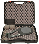
Yes. For in-situ calibration by the user, use the PWC100 (Calibrator for PWS100). There is a separate PWC100 instruction manual.
-
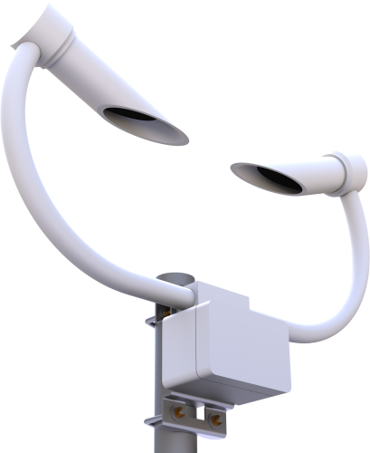
The basic processing current of the PWS100 is <200 mA at 12 V supply. However, the sensor has two levels of heating available. One set of heaters—known as the dew heaters—prevents condensation on the main lenses of the sensor. When these sensors turn on, the current usage increases to approximately 500 mA at 12 V. A current drain of 1 A is the worst case scenario if the input supply to the sensor drops to the minimum of approximately 9 V (the current drain increasing at lower voltages).
By default, the dew heaters turn on all the time and the main hood heaters are off. The dew heaters can be turned off by the user.
The main hood heaters run from a separate power supply and consume 7 A at 24 V when fully on. The main hood heaters only need to be used when icing conditions are likely.
-
The Present Weather Viewer is available for download from the Downloads section of the PWS100 product page.
-
The PWS100 measures the size and velocity of particles in the air. It can provide precipitation rate and water equivalent accumulation, but it is primarily used to report present weather codes, as defined by the World Meteorological Organization and National Weather Service, and particle size and velocity distributions. The PWS100 cannot measure snow depth, as it identifies water droplets in air.