
Competitive price


Overview
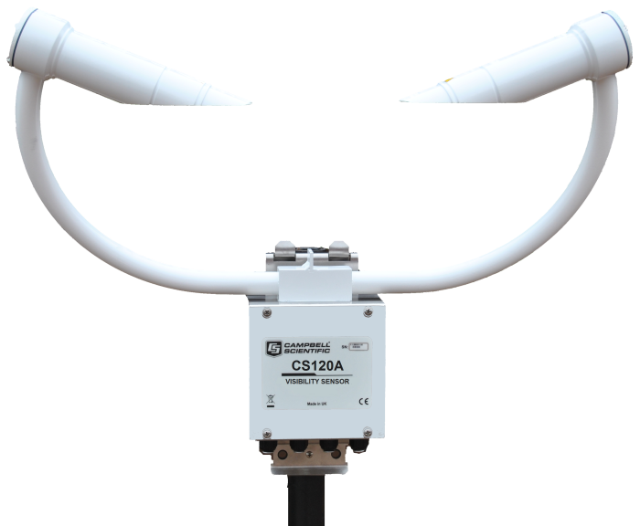
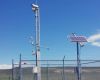
The CS120A uses tried-and-tested, infrared forward-scatter technology, and it uses the proven 42° scatter angle to report meteorological observable range (MOR) for fog and snow in the range of 5 to 75,000 m (16.4 to 246,063 ft). It combines a high specification with a very competitive price. The CS120A is ideal for stand-alone applications or in combination with automatic weather stations in road, aviation, solar-energy, and wind-energy environments.
For aviation applications, users can be assured that the CS120A complies with UK CAA, FAA, and ICAO guidance and meets or exceeds all recommendations and specifications. (This includes CAP437, CAP670, and CAP746.)
The CS120A is certified by Deutscher Wetterdienst as suitable for use to control wind turbine obstruction light systems as specified by 506/04, General Administrative Rules for the Identification of Aircraft Obstructions.
Read MoreBenefits and Features
- High performance sensor at a competitive price
- Three year extended warranty available on this product
- Sensor design minimises airflow disruption at measurement volume
- Incorporates automatic dew and hood heaters for all-weather operation
- Simple field calibration using optional calibration kit
- Low power - suitable for remote application
- Automatic status check for faults or window contamination
- Made in UK
- Type certified for Aviation use by the German Meteorological Service, Deutscher Wetterdienst (DWD)
Technical Description
Compared to many such sensors, the CS120A design means that visibility is being measured in a relatively clean space because the position of the heads and body minimize disturbance of the airflow at the measurement volume.
The CS120A uses continuous high-speed sampling, which improves the accuracy of the measurements taken during mixed weather such as rain and hail, while providing reliable readings during more stable events such as fog and mist. High-speed sampling also allows the sensor to better respond to suddenly changing conditions.
The CS120A has several design features that keep its optics clean. Downward-facing optics minimize dirt and snow buildup. Low-powered heaters prevent the formation of dew, and a higher-powered heater prevents the formation of ice.
The sensor is very power efficient, drawing just 3 W during normal operation including the dew heaters; power can be reduced further by reducing the sample rate and manual control of the heaters.
Two configurable alarm outputs are provided and, via relays, these can drive external warning systems such as lights and fog-horns. They can also be used to switch the intensity of wind turbine warning lights depending upon current visibility levels.
Images
Compatibility
Please note: The following shows notable compatibility information. It is not a comprehensive list of all compatible products.
Specifications
| Signal Type/Output | RS-232, RS-485 |
| Measurement Description | Meteorological Observable Range (MOR) |
| Maximum Reported Visibility | 100 km (62.1 mi) |
| Minimum Reported Visibility | 5 m (16.4 ft) |
| Accuracy |
|
| Resolution | 1 m (3.3 ft) |
| Mounting | Stainless-steel V-bolt bracket that attaches to a pole with a 32 to 52.5 mm (1.25 to 2 in.) outer diameter |
| Electronics Supply Voltage | 7 to 30 Vdc |
| Total Unit Power | < 3 W while sampling continuously (including dew heaters) |
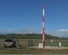
| Standards | Frangible masts are available to customer requirements to meet ICAO recommendations (typically placing the sample volume at 2.5 m [8.2 ft]). |
| Sensor Dimensions | 540 x 640 x 246 mm (21.26 x 25.2 x 9.7 in.) including mount |
| Sensor Weight | ~3 kg (6.6 lb) depending on mounting system |
Optical/Pulse |
|
| LED Center Wavelength | 850 nm |
| LED Spectral Bandwidth | ±35 nm |
| Light Pulse Rate | 1 kHz |
Environmental |
|
| Operating Temperature Range | -25° to +60°C (standard) |
| Extended Operating Temperature Range | -40° to +70°C (This extended version is available as a special. Contact Campbell Scientific for more information.) |
| Operating Humidity Range | 0 to 100% |
| Sensor Sealing | Rated to IP66 |
| Wind Speed | Up to 60 m s-1 |
| Sensor Heater Threshold |
|
DSP & Dew Heaters |
|
| Power | 2 x 0.6 W (total of 1.4 W) for dew heater |
| Typical Current Consumption @ 12 Vdc |
|
Hood Heater |
|
| Supply Voltage | 24 V dc or ac |
| Power | 2 x 30 W (total of 60 W) |
Interface |
|
| Serial Interface | RS-232 or RS-485, 8 bit data bytes, 1 stop bit |
| Serial Data Rates | 1200 to 115,200 bps (38,400 bps default rate) |
Resources and Links
Product Brochures
Manuals
Case Studies
Downloads
CR1000X CS120A example programs v.1 (2 KB) 18-03-2020
CR1000X programs that use the MSSET and MSGET commands.
CS125 and CS120A OS v.17 (555 KB) 08-06-2023
Campbell Scientific has introduced a new operating system, OS 17, for the CS120A visibility sensor and CS125 present weather sensor. It is backwards compatible and is easily installed on all CS120A and CS125 sensors (but not older CS120 sensors). OS 17 is available free of charge and can be downloaded here or supplied by email on request.
Upgrade to OS 17 is recommended.
Case Studies
Exeter Airport is undergoing a huge refurbishment to expand their capabilities and streamline their operations......read more
The Utah Department of Transportation (UDOT) operates a network of roadside weather stations across the......read more
AUDIMOBIL recently installed an Automatic Weather Station in a Portuguese Military Air Base, to support......read more
Articles and Press Releases
Newsletter Articles
Press Releases
Privacy Policy Update
We've updated our privacy policy. Learn More
Cookie Consent
Update your cookie preferences. Update Cookie Preferences