This product is no longer available and has been replaced by: CR350. Some accessories, replacement parts, or services may still be available.

| Services Available |
|---|
Overview
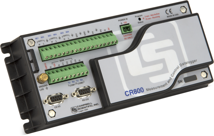
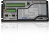
The CR800 is a smaller, research-grade datalogger designed for stand-alone operation in harsh, remote environments. It is intended for smaller configurations in which fewer sensors will be measured. Each CR800 reads input from sensors, then transmits the data via a communication peripheral; most sensors and telecommunication devices are compatible. Multiple CR800s can be configured as a network or units can be deployed individually.
Another datalogger, the CR850, is similar to the CR800, but it has an integrated keyboard and display screen for on-site control.
Read MoreBenefits and Features
- Ideal applications include wind profiling, weather stations, ETo/agriculture, air quality, soil moisture, water level/stage, aquaculture, vehicle testing, Time Domain Reflectometry, SCADA, and water quality
- Simpler in design, the CR800 and CR850 are easier to program and wire.
- Serial communications with serial sensors and devices supported via I/O port pairs
- Contains custom ASIC chip that expands pulse count, control port, and serial communications capabilities
- Compatible with channel expansion peripherals allowing you to expand your system
- Supports PakBus, Modbus, SDI-12, and DNP3 protocols
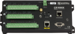
- Includes both an CS I/O port and an RS-232 port for connecting communication devices
- Gas Discharge Tube (GDT) protected inputs
- Battery-backed clock that ensures accurate time is maintained while data logger is disconnected from battery power
- Program with LoggerNet, PC400, or Short Cut to fit your setup
Images


3D/CAD Files:

Technical Description
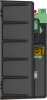
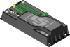
The CR800 consists of measurement electronics encased in a plastic shell and an integrated wiring panel. This datalogger uses an external keyboard/display and power supply. Low power consumption allows the CR800 to operate for extended periods on a battery recharged with a solar panel—eliminating the need for AC power. The CR800 suspends execution when primary power drops below 9.6 V, reducing the possibility of inaccurate measurements.
The on-board operating system includes measurement, processing, and output instructions for programming the datalogger. The programming language, CRBasic, uses a BASIC-like syntax. Measurement instructions specific to bridge configurations, voltage outputs, thermocouples, and pulse/frequency signals are included. Processing instructions support algebraic, statistical, and transcendental functions for on-site processing. Output instructions process data over time and control external devices.
Specifications
| -NOTE- | Note: Additional specifications are listed in the CR800-Series Specifications Sheet. |
| Operating Temperature Range |
|
| Maximum Scan Rate | 100 Hz |
| Analog Inputs | 6 single-ended or 3 differential (individually configured) |
| Pulse Counters | 2 |
| Voltage Excitation Terminals | 2 (VX1, VX2) |
| Communications Ports |
|
| Switched 12 Volt | 1 terminal |
| Digital I/O |
|
| Input Limits | ±5 V |
| Analog Voltage Accuracy | ±(0.06% of reading + offset) at 0° to 40°C |
| ADC | 13-bit |
| Power Requirements | 9.6 to 16 Vdc |
| Real-Time Clock Accuracy | ±3 min. per year (Correction via GPS optional.) |
| Internet Protocols | FTP, HTTP, XML POP3, SMTP, Telnet, NTCIP, NTP |
| Communication Protocols | PakBus, Modbus, DNP3, SDI-12, SDM |
| Idle Current Drain, Average | 0.7 mA (@ 12 Vdc) |
| Active Current Drain, Average |
|
| Dimensions | 24.1 x 10.4 x 5.1 cm (9.5 x 4.1 x 2 in.) |
| Weight | 0.7 kg (1.5 lb) |
Compatibility
Please note: The following shows notable compatibility information. It is not a comprehensive list of all compatible products.
Software
| Product | Compatible | Note |
|---|---|---|
| LoggerNet | (Version 3.3 or higher) | |
| PC200 (retired) | ||
| PC400 | (Version 1.4 or higher) | |
| PCONNECT (retired) | (Version 3.3 or higher) | |
| PCONNECTCE (retired) | (Version 2.2 or higher) | |
| RTDAQ | ||
| Short Cut |
Additional Compatibility Information
Sensors
With several channel types, the CR800 is compatible with nearly every available sensor, including thermocouples, SDI-12 sensors, and 4 to 20 mA sensors. A custom ASIC chip expands its pulse count, control port, and serial communications capabilities. The CR800's I/O ports can be paired as transmit and receive, allowing serial communications with serial sensors and devices.
Measurement and Control Peripherals
The CR800 is compatible with all of our CDMs (requires an SC-CPI), SDMs, multiplexers, vibrating-wire interfaces, terminal input modules, and relays.
Communications
The CR800 communicates with a PC via direct connect, NL201 Ethernet Interface, multidrop modems, phone modems (land line, digital cellular, and voice-synthesized), RF telemetry, and satellite transmitters (Argos, Iridium, and Inmarsat.
Data can be viewed on the CR1000KD Keyboard Display, CD100 Mountable Display with Keypad, user-supplied iOS or Android device (requires LoggerLink), CD295 DataView II Display, or a user-supplied PDA (PConnect or PConnectCE software required).
The SC115 is the only compatible external data storage device. The CR800 does not have a peripheral port and is therefore not compatible with the CFM100, NL115, or NL120.
Enclosures
The CR800 and its power supply can be housed in any of our standard enclosures.
Power
Any 12 Vdc source can power the CR800 datalogger. Power supplies commonly used with the CR800 are the BPALK, PS150, and PS200. The BPALK provides eight non-rechargeable D-cell alkaline batteries with a 7.5 A h rating at 20°C.
Both the PS150 and PS200 consist of a sealed rechargeable 7 A h battery and a charging regulator. Their battery should be connected to a charging source (either a wall charger or solar panel). These two power supplies differ in their charging regulator. The PS150 has a standard regulator and the PS200 has a micro-controller-based smart regulator. The PS200's regulator provides two-step constant voltage charging and temperature compensation that optimize battery charging and increases the battery’s life.
Also available are the BP12 and BP24 battery packs, which provide nominal ratings of 12 and 24 A h, respectively. These batteries should be connected to a regulated charging source (e.g., a CH100 or CH200 connected to a unregulated solar panel or wall charger).
Software
CRBasic, the CR800's full programming language, supports simple or complex programming and many onboard data reduction processes.
Resources and Links
Product Brochures
Technical Papers
- Benefits of Input Reversal and Excitation Reversal for Voltage Measurements
- FTP Streaming
- Preventing and Attacking Measurement Noise Problems
- Voltage Accuracy, Self-Calibration, and Ratiometric Measurements
- BACnet to Modbus Protocol Conversion (App. Note: 1M-C)
- Serial Sensors: Interfacing with CSI Dataloggers (App. Note Code: 2MI-V)
- DNP3 with Campbell Scientific Dataloggers
Case Studies
Compliance
Videos & Tutorials


. A demonstration of one update method that uses a direct connection between a datalogger and a computer, and the Send OS Tab in the Device Configuration Utility.")


. Field maintenance tasks such as viewing and collecting data, setting the clock, and downloading programs are supported.")


 software.")
 output sensors could be used.")


. This activity is helpful when troubleshooting.")


 is a versatile field tool for interrogating and configuring data loggers independently of other communication links. The CR1000KD is invaluable for installing, maintaining, and troubleshooting various data logger applications.")
 is a powerful tool for field use. This video shows simple troubleshooting with the CR1000KD and illustrates how to access real-time and stored data tables using the KD.")


Downloads
CR800 OS v.32.05 (4.38 MB) 06-01-2020
Execution of this download installs the CR800 Operating System and Compiler on your computer. It also updates the CR800 support files for the CRBasic Editor.
Note: This OS has crossed the 2 Meg CR800 size limit for remote download. The OS must be downloaded to the 2 Meg CR800 via direct connect with the Device Configuration Utility. All OS download methods are supported by the 4 Meg CR800.
Upgrading from versions prior to version 28 of the Operating System will reset the datalogger’s CPU drive. This is due to a change in the format of the file system from FAT16 to FAT32. In order for the datalogger to operate correctly, as part of the upgrade, the CPU drive is formatted to FAT32. Any programs stored and running from the CPU drive will be lost. It is not recommended to update the datalogger’s Operating System over a remote connection where program control regulates the communication equipment (turning it on or off, etc.). In these cases, an on-site visit and a backup using DevConfig’s backup utility is necessary to update the datalogger’s Operating System.
Watch the Video Tutorial: Sending an OS to a Local Datalogger.
In all cases where the datalogger is being updated from an Operating System prior to 28, the use of DevConfig’s backup utility is recommended due to the CPU drive being formatted using the new FAT32 format.
Device Configuration Utility v.2.29 (54 MB) 15-11-2023
A software utility used to download operating systems and set up Campbell Scientific hardware. Also will update PakBus Graph and the Network Planner if they have been installed previously by another Campbell Scientific software package.
Supported Operating Systems:
Windows 11 or 10 (Both 32 and 64 bit)
FAQs for
Number of FAQs related to CR800: 158
Expand AllCollapse All
-
1. Connectez l'alimentation électrique au système d’acquisition de données
- Assurez-vous que le câble est branché dans “Power In”
- Pour tester la puissance dans un système d’acquisition qui n'a pas d'ecran, utilisez un multimètre pour tester. (Si l'alimentation est en cours, vous devriez lire environ 12 Volts)
2. Télécharger le pilote
- Si vous avez acquis le système d’acquisition de données de chez Campbell Scientific, un CD a été fourni avec le logiciel du pilote.
- Si vous n'avez pas le CD, Vous pouvez télécharger la dernière version du pilote a www.campbellsci.ca/l17394.
- Si vous avez acquis le système d’acquisition de données d'un autre fabricant, Vous devez télécharger la dernière version du pilote de leur site Web.
3. Ouvrez le Gestionnaire de périphériques
- Dans le menu Démarrer de Windows, accédez -> “Device Manager” -> “Ports”
- Si le programme “Device Manager” est bloquée, vous avez besoin d’obtenir les autorisations nécessaires de l'administrateur informatique.
- Si l’icône ci-dessous apparaît, cela signifie que le pilote n’été pas installée correctement et doit être réinstallé.
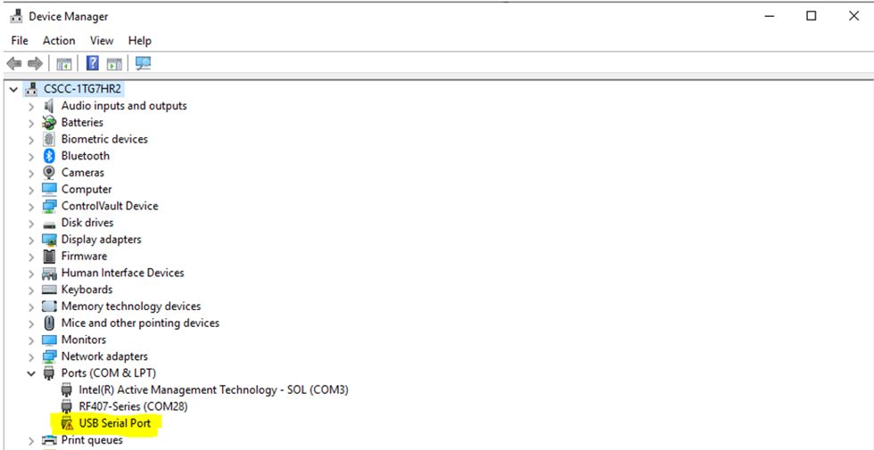 4. Tester le cable
- Pour s'assurer que le câble fonctionne correctement, connectez l'extrémité de ce câble dans un port USB de votre ordinateur.
- Si “USB Serial Port” apparaît sous l’onglet “Ports” mentionné ci-dessus, le câble fonctionne correctement.
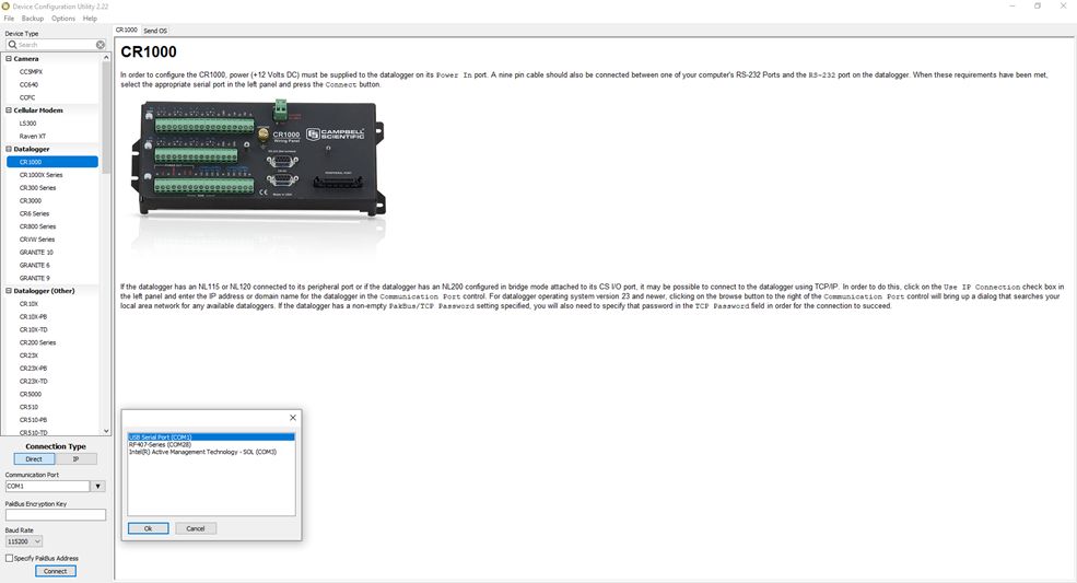
5. Connecter avec un système d’acquisition de données- Dans le menu démarrer de Windows, accédez -> “Device Configurator” -> “Utility”-> Dataloggers -> Select your Device
- Connection type -> Direct
- Communication port -> USB serial port -> ok -> Connect.
 6. Impossible de se connecter avec un système d’acquisition de données
- Garder le programme “Device Configurator” ouvert-> retiré le cordon électrique -> cliquer sur “Connect” -> connectez le câble d'alimentation.
Si vous ne parvenez pas à vous connecter au système d’acquisition de données, n'hésitez pas à contacter notre équipe de support technique expérimentées par courriel à support@campbellsci.ca, ou par telephone à (780) 454-2505. -
The potential transformer and the current transformer provide differential outputs that have galvanic isolation from the voltage and current in the circuit they are measuring. However, there is no need to run the outputs of these transformers into differential inputs of the data logger and unnecessarily consume additional data logger channels. We conducted extensive testing for noise immunity, for inaccuracies from ground loops, and more before concluding that single-ended measurements in the ACPower() instruction have the same performance as differential measurements would provide. Please note that as a result of the galvanic isolation of the potential transformer and current transformer, the data logger ground is NOT connected to the ground of the circuit they are measuring.
Said differently, you can connect differential outputs of a sensor to single-ended inputs of the data logger. However, doing so creates the possibility of poor common-mode noise rejection in the data logger and the possibility of introducing inaccuracies from ground loops between the sensor and the data logger. Note that in this application, the transformer isolation of the potential transformer and the current transformer eliminates these concerns.
Simply connect one of the potential transformer secondary wires and one of the current transformer secondary wires to the data logger ground. Which wire in either case makes a difference, as the phase information allows the measurement of power flowing in either direction. If you measure negative real power when it should be positive, then reverse the secondary wires of the potential transformer where they connect to the data logger. Alternatively, you can reverse the secondary wires on the current transformer, but don't reverse both pairs of wires.
-
Yes, but it is difficult and time consuming. The display is best used to make small changes in an existing program already installed in the data logger.
-
The 5 V terminal is regulated and remains near 5 Vdc (±4%) as long as the CR800 supply voltage remains above 9.6 Vdc. Measurement of the output from 5 V (by means of jumpering to an analog input on the same CR800) enables an accurate bridge measurement if the 5 V terminal must be used for excitation.
-
Yes, unless the CR1000 program contains measurement instructions for channels not available on the CR800 or CR850.
-
Yes. EX and VX are synonymous and refer to voltage excitation.
-
Yes. The CR800 and CR850 are compatible with exactly the same options as the CR1000 but with a lower channel count.
-
The data logger can store multiple programs; however, one program is capable of supporting all sensors simultaneously. A dedicated program for each sensor is unnecessary and would not be practical to implement.
Case Studies
Background In 2022, ECR Medio Ambiente assumed the responsibility of overseeing the structural monitoring installation at......read more
International partnerships for sustainable innovations Improved water use in agriculture is essential to successfully adapt to......read more

Southwestern South Africa had three consecutive dry winters—from 2015 through 2017—resulting in the Cape Town......read more

Summary Problem The University of Birmingham had set up and was operating 26 weather stations across the......read more
In August 2012, RESPEC was contracted to provide field instrumentation and early-warning monitoring services at......read more
The Silkwood sugarcane water-quality monitoring site was established in 2014 as part of the Paddock......read more
The Silkwood sugarcane water-quality monitoring site was established in 2014 as part of the Paddock......read more
In February of 2015, Campbell Scientific was awarded a bid to supply the Harris County......read more
Listed Under
Privacy Policy Update
We've updated our privacy policy. Learn More
Cookie Consent
Update your cookie preferences. Update Cookie Preferences