How to Easily Replace and Update a CS223 Sensor Head
by Ajay Singh | Updated: 01/15/2024 | Comments: 0
Blog Topics
Area / Application


Product Category


Corporate / News
Search the Blog
Subscribe to the Blog
Get an email when a new article is posted. Choose the topics that interest you most.
Suggest an Article
Is there a topic you would like to learn more about? Let us know.
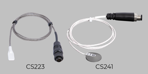
Campbell Scientific’s CS223 Pt-1000 Class A, Back-of-Module Temperature Sensor (discontinued effective 31 October 2023) has been replaced by the CS241 Pt-1000 Class A, Back-of-Module Temperature Sensor. When needed, you can replace the CS223 sensor head with a CS241 head without having to replace the entire cable. This blog article explains the steps to take so you can use the existing cable already installed in the field.
Configurations for the CS223
The CS223 was available in two configurations. Check to see which one you have, as the instructions for replacement are somewhat different.
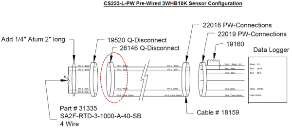
CS223-L-PW
This configuration used prewired connectors, which was most preferred by our customers as it minimized the need for wiring in the field. The configuration consisted of three parts:
- A sensor head with a small cable with a Q-Disconnect connector (pn 19520)
- A home run cable connecting the sensor with the enclosure containing the data logger. The cable had pn 26146 D-Disconnect mating connector to the part in (1) above and another connector (pn 22018) that mated with a bulkhead connector mounted on the enclosure.
- The bulkhead connector (pn 22019) mounted on the enclosure that had a high-precision 1,000 ohm (pn 19160) completion resistor soldered on it. All necessary connections between this connector and the data logger are done at the factory.
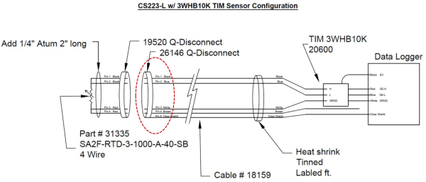
CS223-L-TIM
This version used the 3WHB10K Terminal Input Module (TIM) for the completion resistor and did not use a bulkhead panel-mount connector. The customers had to complete the field wiring themselves. The parts in 1 and 2 above were the same. The parts in 3 were not used. A wiring diagram is shown below.
Converting the CS223 Sensor Head to a CS241 Sensor Head
For the conversion, you will need pn 32932 and a circular, plastic, M12-type socket, eight-pin connector sold as a kit (pn 39570), also referred to as the CS241 field install kit for CS240 replacement.
You will need this if you want to use the existing cabling but want to replace the CS223 with a CS241.
Steps for CS223-L-PW
- Cut the Q-Disconnect connector from the end facing the sensor. This is shown in the red circle in the diagrams above. Please cut the connector as close to the end as possible. You can also watch our M12 Connector Field Install Kit video.
- Remove the outer insulation jacket carefully to about 1”.
- Strip the individual wires about 1/4”.
- Connect the wires to the connector pins as follows:
Wire Color Pin on the Connector Data Logger White 1 ⏚ Blue 3 SE-L Gray 4 SE-H Black 5 Excite (Vx1) - Cut off the connector on the other end of the cable and land the conductors directly to the data logger. (See the table above.)
Steps for CS223-L-TIM
- Cut the Q-Disconnect connector from the end facing the sensor. This is shown in the red circle in the diagrams above. Please cut the connector as close to the end as possible. You can also watch our M12 Connector Field Install Kit video.
- Remove the outer insulation jacket carefully to about 1”.
- Strip the individual wires about 1/4”.
- Connect the wires to the connector pins as follows:
Wire Color Pin on the Connector Data Logger White 1 ⏚ Blue 3 SE-L Gray 4 SE-H Black 5 Excite (Vx1) - Remove the TIM module and connect the wires to the respective data logger channels directly.
- Install a jumper between the Excite channel and SE-H channel used. You don’t need the TIM module, as the CS241 comes with a completion resistor installed inside the M12 connector.
Please use the following lines of CRBasic code for a CR1000X Measurement and Control Datalogger to read the sensor:
Public RRTD
Public BomT
DataTable (Test,True,1000)
	DataInterval (0,1,Sec,10)
		Sample (1,BomT,FP2)
EndTable

BeginProg
	Scan (1,Sec,0,0)
		BrHalf3W (RRTD,1,mV1000,1,Vx1,1,500,True ,0,60,1000,0)
		PRTCalc (BomT,1,RRTD/1000,1,1.0,0)
	CallTable Test

NextScan

EndProg
Final Words
In case you have some other variation, you can still use the methods outlined here and a good digital handheld multimeter to troubleshoot, just in case. You can also reach out to us by contacting our support staff, and we will be happy to help you.


About the Author
 Dr. Ajay Singh is a Product Manager in the Renewable Energy Group at Campbell Scientific, Inc. His work is focused on PV soiling measurement and mitigation, solar resource assessment, and solar radiation measurement. He has a doctoral degree in physics.
Comments
Please log in or register to comment.